Earlier this year, I found myself thinking about a beginner friendly homebrew rig, and what that would look like if I were designing for my younger self. There have been many designs published that aim to fill this role, with varying degrees of success. There is a balance to strike for such a rig between simplicity and functionality. On the one hand, the bare minimum requirement to make contacts might be little more than a crystal oscillator and a single FET regenerative receiver, but even experienced operators would find this an extremely challenging setup to use on a regular basis. Younger hams with less experience are more likely to be turned off by such an experience than motivated to keep pursuing homebrew and QRP. On the other hand, it’s easy, as we design and build these rigs, to let “feature creep” get the better of us. A rig that is nominally targeted towards the beginner builder can end up having so many “bells and whistles” that the schematic becomes overwhelming for beginners, perpetuating the idea that homebrewing is only for an elite few. A beginner-friendly homebrew rig, then, should strike the balance between being so simplistic that it ceases to be useful on the air (I’m looking at you, PIXIE…) and so complex that potential builders are scared away before even starting. What follows is my take on a simple CW transceiver that is practical for daily casual operating, but simple enough for the beginner builder. CW was chosen both for easier design and construction and for its efficiency at QRP power levels.
As I thought about the specific design goals for the rig, there were a few features that I knew I wanted to include.
* PLL frequency control - My number one design criteria was to use the si5351a, along with an MCU like the Arduino or Pi Pico for frequency control. The si5351a has three outputs that can be independently controlled to output a square wave from 8 kHz to >150 MHz. It is both stable and frequency agile. No need to make new builders struggle with operating crystal-controlled rigs. From a construction point of view, building the Arduino/si5351a combo is scarcely more complicated than building a crystal oscillator, which is what I often see beginners instructed to do, and is much more useful.
* Direct Conversion Receiver - in the interest of simplicity, I opted for a direct conversion receiver. It provides ample sensitivity and a clean sound that is difficult to replicate with a superhet receiver. Also, it eliminates the need to worry about building or buying IF filters.
* Solid State T/R switching - Solid State T/R switching is a small detail that can make the difference between a CW rig that is a joy to operate, and one that fatigues you quickly. Nobody wants to listen to the constant chatter of a relay, or even worse, be constantly switching a manual switch.
* At least 1 Watt of Output - Everyone seems to have a different power level that they consider the minimum to consistently make contacts. Hardcore Milliwatters might scoff at anything over 1 watt, while others may want 5 watts. My personal experience is that with 1 watt and a reasonable antenna, I can consistently make contacts with good signal reports, depending somewhat on the band and conditions (more on band choice later.)
* 30 Meter Band - I needed to decide on what band to build for. 40 meters is a perennial favorite for QRP activity and with good reason. It’s nearly always open. With the current sunspot cycle, higher bands like 20, 15, or 10 were also tempting. I ultimately decided on 30 meters, which I consider to be the perfect band for a rig like this. 30 meters, like 40, is open to somewhere nearly all day, and much less cyclical than 20. 30 Meter antennas are smaller and more manageable than 40 meter antennas. Also, 30 meters has a 200 W PEP output limit and no contests, making it an ideal band for casual QRP CW. For those that would prefer 40 meters, changing the band is a simple matter of rescaling the bandpass and lowpass filter, then changing a few lines of code. Alternate component values are provided in Table 1.
* Use Commonly Available Parts - As much as possible, I wanted to use parts that are cheap and readily available. All transistors are garden-variety small signal NPN or switching MOSFETs. All of the ICs are cheap and readily available from numerous sources. The MC1496 product detector, while probably not in everyone’s junkbox, was chosen for its price and because it is much easier to get than the more well-known NE602.
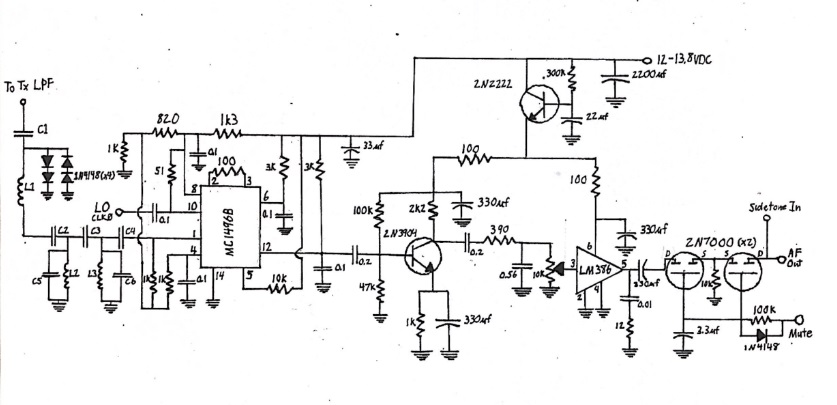
With these basic goals in mind I started with some block diagrams and then built the receiver portion. The receiver starts with a 2nd order doubly terminated bandpass filter centered on 10.1 MHz. The signal then passes into the product detector stage, based around the MC1496.
The MC1496 is an older IC that essentially consists of a Gilbert Cell Mixer. It is functionally very similar to the NE602. I decided to use this part for a few reasons. First, it’s cheap, and readily available in a through-hole DIP package. Second, it eliminates the need for winding transformers for a diode ring mixer. Third, it provides modest conversion gain, reducing the gain requirements for the AF portion of the receiver. Unlike the NE602, most of the biasing for the MC1496 is external, meaning that it does require more external resistors to set up. The schematic for the product detector section is pulled almost directly from the datasheet.
The audio section starts with a common emitter preamplifier that is fully bypassed at audio frequencies. The output from the preamplifier feeds into a very simple lowpass audio filter with a 3 dB rolloff at 730 Hz. The purpose of the filter is not so much to provide audio selectivity as to roll off the high frequency signals above 2 or 3 kHz. While it does little to nothing for selectivity, it does make the receiver much more pleasant to listen to.
The final amplifier is an LM386 with the schematic again pulled directly from the datasheet. There are undoubtedly better parts available, but the goal here was to utilize the most readily available parts. Importantly, the infamous gain boost capacitor between pins 1 and 8 is omitted. The extra gain is not needed, and omitting the gain capacitor greatly reduces noise.
Both the audio preamplifier and audio amplifier are powered from an active decoupling circuit borrowed from W7EL’s “Optimized QRP Transceiver” schematic. This simple circuit helps prevent noise from the Vcc line being picked up and amplified by the high gain audio stages.

For the transmitter section, I went back to the same design that I used for my main rig a couple of years ago. It is simple, easy to build, and relatively rugged. The si5351a is keyed via the Arduino to provide the oscillator. This is then fed into a 74HC04 hex inverter as the buffer and driver amplifier. The signal is fed into the first inverter gate, whose output is then fed back into the other 5 gates connected in parallel. The output of the 5 parallel gates has an impedance of around 12-15 ohms as measured on my oscilloscope. This is sufficiently low to directly drive the base of the NPN Class C final amplifier. The final amplifier consists of 3 TO-92 2N2222a transistors in parallel running class C to a 50 ohm load on the collector. Each of the transistors has a small piece of copperclad PCB epoxied to the flat side of the case as a heatsink. The output from the collectors is then run through a 5th order Chebyshev lowpass filter to the antenna. This transmitter is broadband by design, and I have used this exact lineup successfully on 80-15 meters. Because of its broadband nature, low pass filtering at the output is a must.
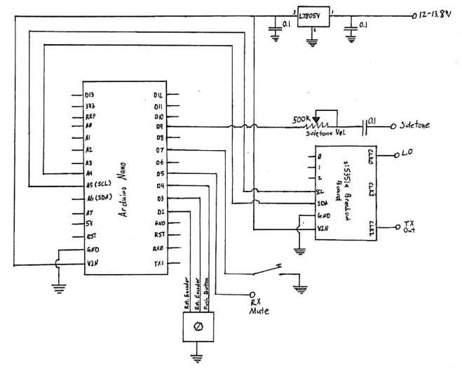
One of the keys to the simplicity of the schematic is to utilize the Arduino as much as possible for features that would otherwise require extra hardware. The Arduino controls keying, frequency output, sidetone, and sequencing for the T/R switching, besides controlling the si5351a. Most of these features are accomplished directly from the Arduino’s I/O pins. The heart of this section is the Arduino Nano. There has been a push recently to move away from the ATMega328P-based MCUs to more capable options like the ESP32 or the Raspberry Pi Pico and its variants. All of these MCUs are more than capable and would make fine substitutes. I chose the Nano because it’s what I had sitting in my junkbox, and I already had some code for it to drive the si5351a. The si5351a board is controlled by I2C from pins A4 and A5, controlling the data and clock lines, respectively. Both boards receive power from a 5V regulator mounted on the digital board.
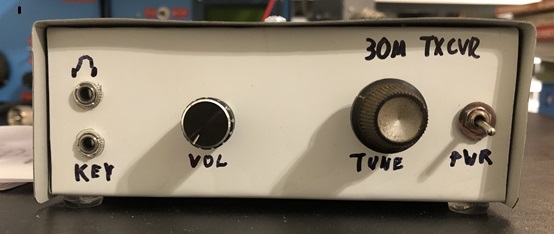
One obvious omission with this section is the LCD or OLED display to show frequency. I elected to use a different method of frequency output for this rig. I wanted the front panel to be simple and easy to fabricate. Round holes are easy enough for anyone with a hand drill, but the large square cutout for a display can be a bit more challenging! Also, I didn’t want the current draw of a backlight or the inconvenience of having to tilt the panel to the right angle to read it. Instead, the frequency is sent in morse via the sidetone output when the center button is pushed on the rotary encoder. The code is set to truncate the first three digits, only sending the last one or two since they are the only ones that will change. For instance, “10.105” would be sent as just “5.” Similarly, “10.115” would be sent as “15.” I’ve found that this is both functional and unobtrusive for a small rig like this.
The Nano also controls muting and does some rudimentary T/R sequencing. When the transmitter keyed, the Nano first mutes the audio output through pin D7, then disables the clock output to the receiver product detector, then enables clock output to the transmitter, then enables sidetone. On key up, the process essentially happens in reverse. This helps keep the sidetone clean and free of any pops or thumps when keying.
Muting is handled by a pair of 2N7000 mosfets at the output of the LM386 audio amplifier. I found that when placed at the input of the LM386, which is more conventional, the LM386 was picking up RF on transmit and causing a noisy, harsh sidetone during sending. While a different layout or more isolation between modules might have helped this, I found that simply muting the output completely cured the problem. Sidetone from the MCU is injected right at the output of the mute switch. Sidetone volume may be adjusted from the trimmer pot on the digital board.
https://github.com/KI4POV/SC-30
I won’t go into great detail here on the code, but I’ll give some general comments on it. First, my code to drive the si5351a and read the rotary encoder is based on a sketch that Charlie Morris, ZL2CTM wrote and published on his blog. I’ve used his code as the base for nearly every rig I’ve built, adding and modifying to suit my needs. I’ve tried to comment the code well to make it readable and easy to follow.This sketch uses the Etherkit si5351a library written by Jason, NT7S, who deserves much credit for making this part easy to use for the average builder. I also used his Etherkit Morse library for the morse frequency output. I was not familiar with this library until I started doing research for this project, but this is a powerful library that has all kinds of applications for beacons, keyers, etc.
The tuning step is set to 50 Hz by default. For simplicity’s sake, I have not included a way to adjust this externally as I found that 50 Hz was about the right step to tune through the band smoothly and not have it sound jumpy, but also tune across the band reasonably quickly. This can, of course, be changed in code to whatever tuning step you would like.
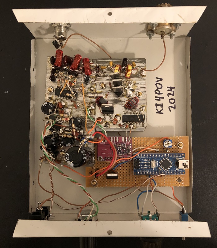
This transceiver was designed and built in three distinct modules: the digital board, the transmitter, and the receiver. I highly suggest that the rig be built in this order. Building the digital board first will give a tunable oscillator that can be seen on an oscilloscope or heard on the station transceiver. Once the digital board is completed, the builder has a choice of whether to build the transmitter or receiver board first. The transmitter board is far simpler, and can be built in an evening. This, combined with a simple manual T/R switch can be used with an existing receiver to start making QSOs with your own homebrew transmitter. The receiver can then be built on a separate board and attached to the transmitter board to complete the transceiver.
Both the transmitter and receiver boards are built “ugly” style, with the ICs on their back “deadbug” style. The digital board is built on perf board. The transmitter and receiver "boards" are actually built on pieces of tin plate soup can that has been carefully cut out and hammered flat, hence the name SC-30 (short for Soup Can-30). I don't necessarily recommend cutting up soup cans unless you have some very thick gloves and good eye protection, but the resulting tin plate is very easy to solder to.
For the receiver section, I highly suggest starting with the LM386 audio amplifier. Once this stage is built, it can be tested simply by connecting a speaker and power. The builder should hear a hum in the speaker when touching the input on pin 3. Once that has been built and tested, the 2N3904 preamplifier stage can be added and tested in the same way.
While not terribly difficult, building the MC1496 product detector stage is probably the most challenging part of the assembly. If this “beginner-friendly” build has a short-coming, it is the need to set up external biasing resistors for the MC1496. Due to the physical layout of the IC, there are a couple of resistors that need to cross over the IC body. There are at least two ways to approach this. If the builder is comfortable with perf board construction, this shouldn’t present any great challenge. I elected to build the section “dead-bug” style to integrate with the ugly construction for the rest of the RF sections. I recommend that the builder snip off pins 7, 9, 11, and 13 of the MC1496, which are all “N/C,” or no-connects. They serve no function and removing them makes the other pins better spaced and easier to solder to. Once that was done, I placed the chip on its back with the 8-14 pin side facing the audio preamp. Solder pin 14 directly to the ground plane to anchor it while you build the rest of the stage. For the resistors that need to cross over the body of the chip, some short lengths of insulated hookup wire make wiring much easier.
Operation of the transceiver is simple, but perhaps some brief explanation is in order for those who have never operated a direct conversion transceiver before. The transmitter frequency is the frequency that is output on the sidetone frequency output. The receiver frequency is offset 650 Hz higher to account for the necessary offset for CW. Because the receiver is direct conversion, the signal being tuned in will be audible on both sides of zero beat. In order to properly tune in a station, it is necessary to tune to the upper signal. This means either tuning from the top of the band down, or tuning through zero beat to the upper sideband. This sounds more complicated than it is, and anyone who has used a Heathkit HW-8 will be familiar with this operation. Once you are listening to the right sideband, the station can be zero-beated by pushing the frequency readout button and matching the station’s tone to your sidetone. The code is set so that the receiver offset and the sidetone are both 650 Hz. Of course, because of the 50 hz tuning steps, you may not be able to exactly match the other station, but I’ve found that 50 Hz is close enough for most operators.
This rig is a definite step up from the “toy” transceivers that we sometimes see. (Don’t get me wrong, I enjoy those too!) I have had many solid ragchew QSOs within the continental US with this rig. My best DX so far has been Belgium when he replied to my CQ on what I thought was a dead band!
My goal was to build a simple transceiver that prospective builders could build in modules. I estimate the total parts cost for this rig to be >$30 if all parts are bought new. A reasonably well-stocked junkbox would reduce that price significantly. I make no claims that this is the end-all be-all in performance, but it is functional enough to use on a regular basis without the frustration of being rockbound.
For the experimenter, the possibilities for expansion and modification abound. Some ideas include:
* adding an LCD
* RIT
* Additional audio filtering
* Other product detectors (diode ring, cascode JFET, etc)
* Adding a keyer to the Arduino code
The basic architecture can be used as a testbed for all sorts of ideas.
I should acknowledge a couple of people before closing. While I did not consult him for the building of this rig, Pete Juliano has been a great resource for me (and many others!) and in particular has helped to bring the previously obscure MC1496 back into public consciousness with his use of it in several projects. The muting circuit used in the receiver is taken from G4TGJ’s excellent webpage. I’d also like to thank Pete Eaton, WB9FLW, who encouraged me to finish this article and graciously provided his proofreading services.
One final note, I’m neither an engineer nor a programmer. I’m a pharmacist by day. For the readers who are thinking “there’s a better way to do _____”, you are almost certainly right. That being said, it does work, and hopefully will encourage prospective builders who don’t have a professional background in electronics to venture into homebrew.
Will-KI4POV
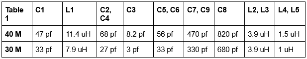
*For the 30 meter version, L1 39 turns wound on a T50-2 core. L2 and L3 are 27 turns wound on a T50-2 core. L4 and L5 are 14 turns wound on a T37-6 core. Note that if you use the popular toroids.info website to calculate the number of turns, it will recommend more turns than I used. I find that the online calculator tends to overestimate the necessary number of turns slightly. My recommendation is to wind the number of turns recommended by the calculator, then use an LC meter or a NanoVNA to adjust turn spacing or remove turns until the desired inductance is reached.*